Michelson Interferometer
 par turbomoskal


Fichiers imprimables (9)
-
 stl
stllower_base.STL
2.7 Mo · 22 téléchargements
-
 stl
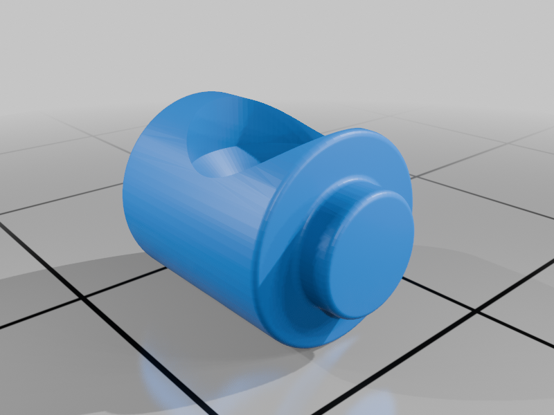
stllower_bushing.STL
624 Ko · 17 téléchargements
-
 stl
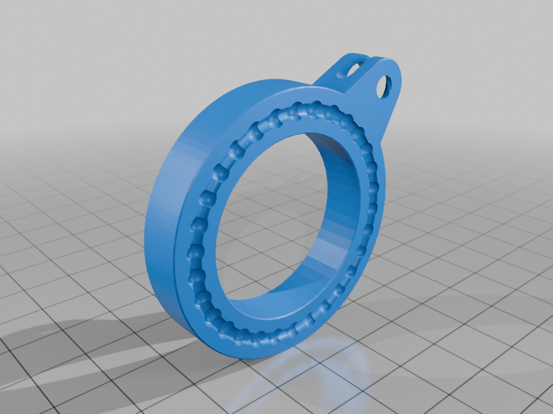
stlcube_turntable.STL
2.3 Mo · 18 téléchargements
-
 stl
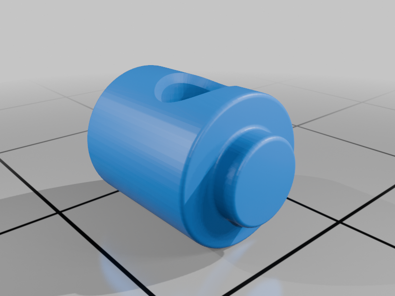
stltable_bushing_nut.STL
379 Ko · 18 téléchargements
-
 stl
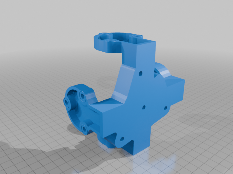
stlupper_base.STL
1.4 Mo · 18 téléchargements
-
 stl
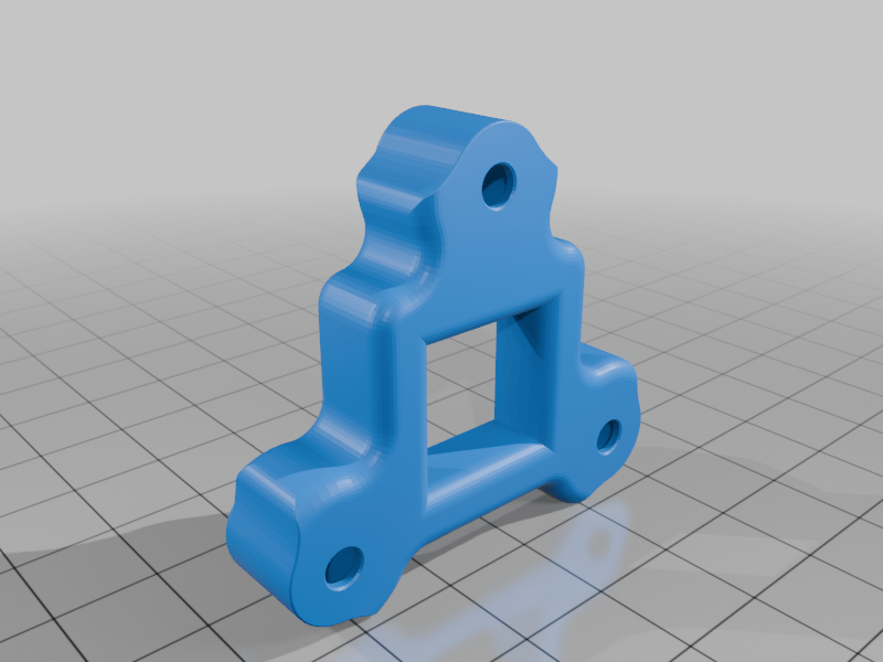
stlcube_base.STL
1 Mo · 20 téléchargements
-
 stl
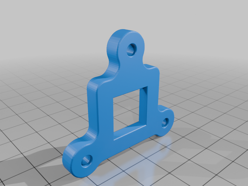
stlmirror_base.STL
559 Ko · 18 téléchargements
-
 stl
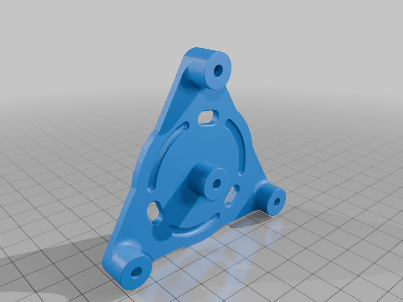
stllaser_base.STL
830 Ko · 17 téléchargements
-
 stl
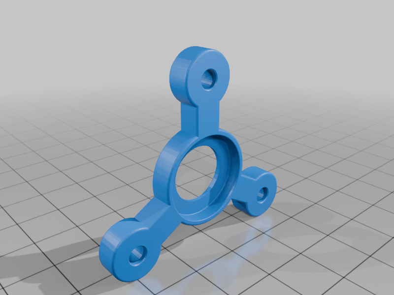
stlmount_part.STL
116 Ko · 17 téléchargements
Description
One of my trauma-driven development masterpieces. It has a 13 calibrating screws! (3 for each of two front-face mirror planes, 3 for laser plane, 3 for beamsplitter plane and last one for beamsplitter rotation). So it's very hard and (not so) fun to calibrate this interferometer. And it's very-very sensitive to literally any vibrations around itself. But working!
BOM:
45x d=3mm bearing balls;
18x M3x5x5mm heatset inserts;
1x M3 nut;
13x D=4.5mm L=10mm d=0.4mm spings (or any other compatible);
15x NFE 27-619 washers;
15x D=5.1mm L=9mm d=3.5mm bushings (optional);
16x M3x20 DIN965 Torx (or any other ISO 10642) screws;
Silicone grease;
1x M52x0.75 lens filter base (optional);
1x K9 (or any other optical or not so) glass 20x20x20 beamsplitter;
2x 20x20 front-face mirrors;
1x 100mW (may be less powerful) red (or any other color) laser in similar casing as mine.
Build:
- Print lower_base, lower_bushing, cube_turntable and table_bushing_nut. Insert heatsets, grease bearing ball guides (massive one in cube_turntable and lower_base). Install 30x (full ring side) bearing balls in cube_turntable and place it into lower_base. Then insert with some grease lower_bushing in lower_base and table_bushing_nut in cube_turntable. And insert M3 nut into *table_bushing_nut**;
- Print upper_base and cube_base. Place last 15x bearing balls into cube_turntable with grease and install upper_base. Screw it with x3 M3x20 screws and 3x NFE 27-619 washers. Insert 3x bushings into cube_base then add washers and screws and place springs on screws. Attach and screw it to cube_turntable. This is beamsplitter plane;
- Screw lower_bushing and table_bushing_nut with M3x20. This is beamsplitter rotation;
- Print 2x mirror_base and insert heatsets. Install bushings, screws and springs in lower_base as depicted and screw it. This is mirror planes;
- Print laser_base and do same action as previous. This is laser plane.
If you want to attach interferometer to DSLR camera, use 3x mount_part and M52 lens filter base.
Calibrating:
Repeatedly calibrate each of planes then cube rotation until you get good circle interferention picture. Good luck with it!
Printing:
I used Flashforge AD5M (0.4mm nozzle) with given parameters:
- Layer 0.12mm;
- Infil gyroid 15-20%
- Wall 3-4 lines;
- No supports.
Sources:
All files created in Solidworks 2021.