Rollingstep Walker


Fichiers imprimables (13)
-
 stl
stlfoot.stl
43 Ko · 1 457 téléchargements
-
 stl
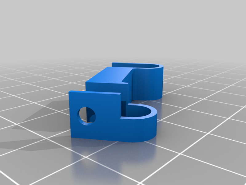
stlrocker.stl
47 Ko · 1 452 téléchargements
-
 stl
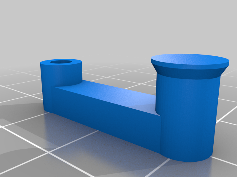
stlbar.stl
43 Ko · 1 461 téléchargements
-
 stl
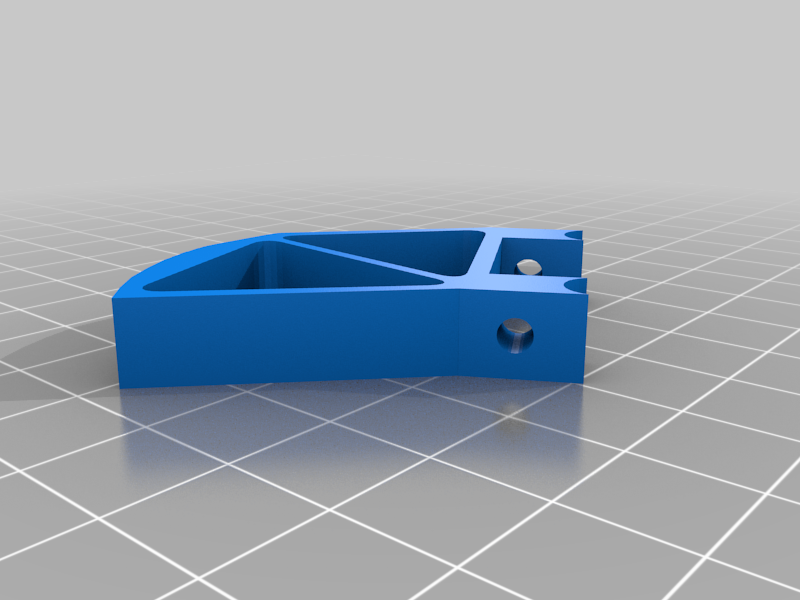
stlcrank_support.stl
102 Ko · 1 451 téléchargements
-
 stl
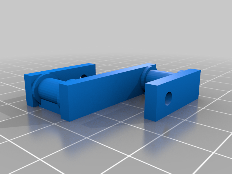
stlcrank.stl
68 Ko · 1 453 téléchargements
-
 stl
stltopframe.stl
32 Ko · 1 460 téléchargements
-
 stl
stlframe1.stl
107 Ko · 1 454 téléchargements
-
 stl
stlframe2.stl
117 Ko · 1 450 téléchargements
-
 stl
stlgear1.stl
93 Ko · 1 444 téléchargements
-
 stl
stlgear2.stl
284 Ko · 1 436 téléchargements
-
 stl
stlgear3.stl
277 Ko · 1 438 téléchargements
-
 stl
stlgear4.stl
188 Ko · 1 441 téléchargements
-
 stl
stlgear5.stl
237 Ko · 1 440 téléchargements
Description
We already know the Klann linkage, Theo Jansen / Strandbeest linkage, Chebyshev Lambda / Plantigrade, Ghassaei, Strider, Trotbot, and many more, which are all designs for walking mechanisms using single rotating crank and several bars connected with hinges. I tried yet another mechanism, using the common 4 bar linkage but with the foot link shaped such that the contact point is not constant. While the movement is advancing, different parts of the foot will touch the ground, like the heels and toes of human foot. This is similar to the rolling step technique used by marching bands, hence the name.
A vehicle could be propelled with 8 legs. I printed two copies of half a vehicle and mounted them on an acrylic plate. For the electric parts I used 2 DVD spindle motors, 2x 18650 lithium batteries, Arduino nano, HC-05 bluetooth, and robot controller board with 2 H-bridges.
Video:
https://youtu.be/hQ1YsS6fH44
The linkage bar lengths and foot shape are not optimized yet, this is just a first prototype. You are free to modify this and find a better design (and perhaps a proper research and publication).
Print list: fot half a vehicle
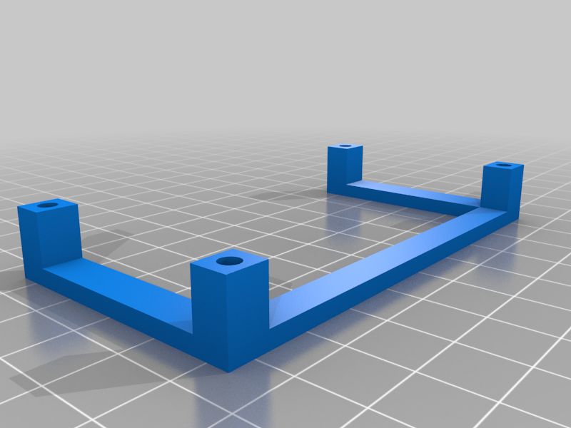
topframe x1 <-- all holes 3 mm diameter
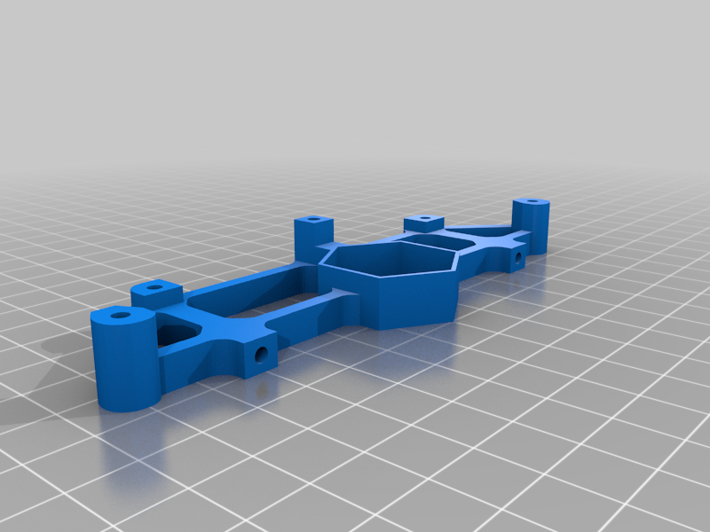
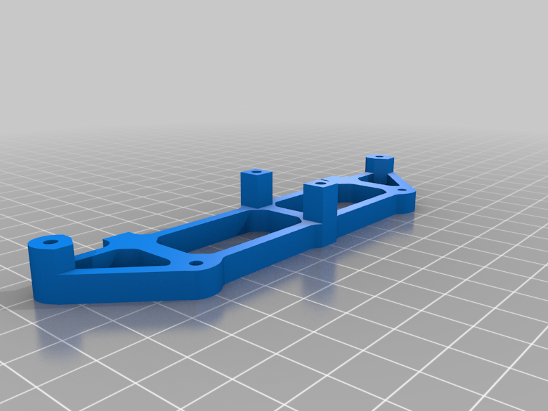
frame1 x1 <-- all holes tapped for M3 screw
frame2 x1 <-- all holes tapped
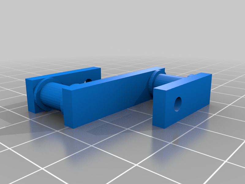
foot x4 <-- 3 mm hole
bar x4, 2 mirrored, 3 mm holes
rocker x4 <-- 3 mm hole
crank x2 <-- 3 mm hole
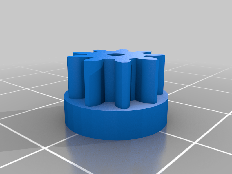
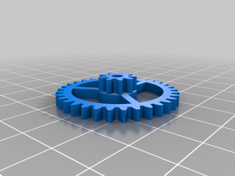
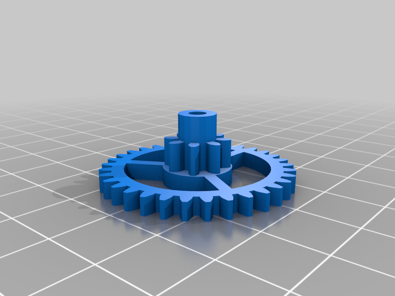
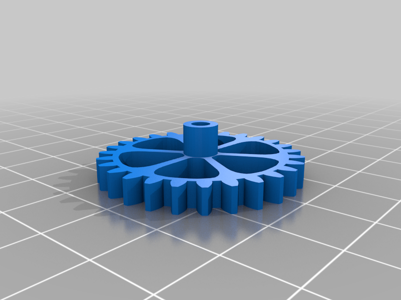
gear1 x1 <-- 2 mm hole for motor shaft
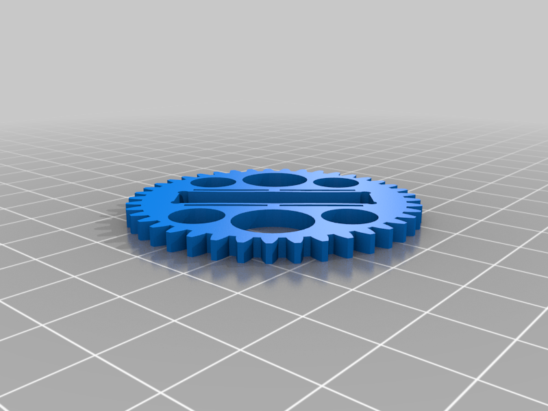
gear2, gear3, gear4 x1 <-- 3 mm hole
gear5 x2
All screws used are M3 with lengths 40mm, 25mm, 20mm, 12mm, 10 mm. After printing, I need to clean the screw holes with drilling and form the thread with tapping, and several hours of whittling for the gears.
Only "crank.stl" needs support but I included "crank_support.stl" which already includes manual supports (which sticks somewhat to the part, i removed them with pliers).