27/05/2026
FDM Part Optimization
Optimize your FDM 3D prints by reducing mechanical anisotropy. This practical guide explains how to improve the strength and inter-layer adhesion of your parts using 3 key levers: Meta description: How to reduce mechanical anisotropy in FDM 3D printing? Optimize your part orientation, infill pattern, and extrusion flow. In brief: This technical guide analyzes the structural weaknesses related to layer stacking in FDM and proposes three
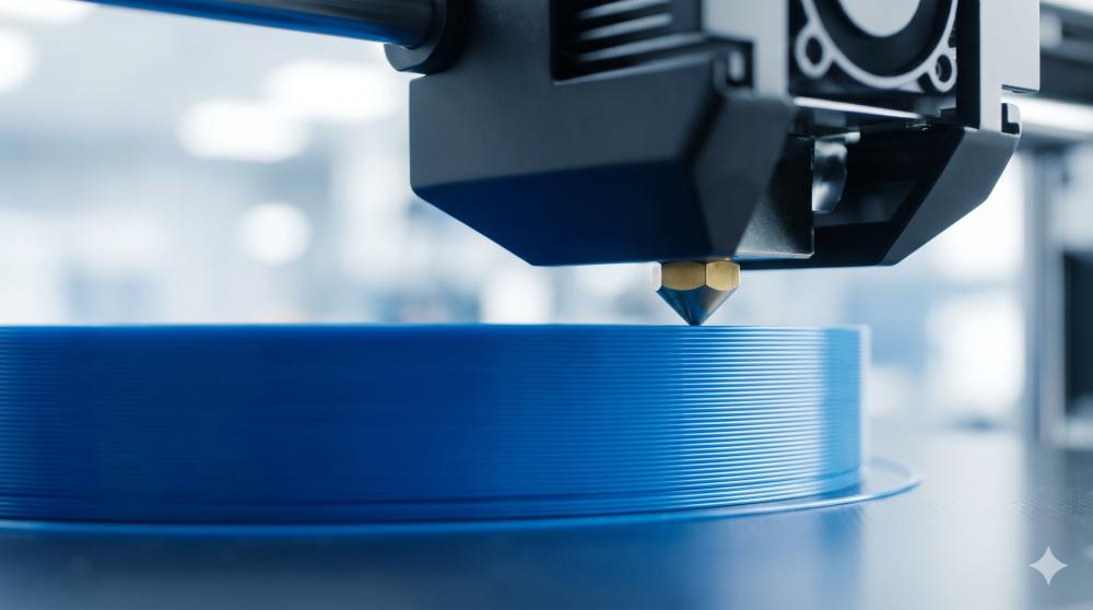
Fused Deposition Modeling (FDM) 3D printing has revolutionized prototyping and manufacturing. However, one of its main limitations lies in the mechanical anisotropy of the produced parts. Unlike isotropic materials (whose properties are uniform in all directions), FDM parts often exhibit varying strength and stiffness depending on the axis of applied stress. This article explores how to reduce this anisotropy by optimizing three key levers: part orientation, infill parameters, and flow modifiers.
Understanding Mechanical Anisotropy in FDM
Mechanical anisotropy in FDM is a direct consequence of the extrusion process and the layer-by-layer stacking of filaments. Inter-layer fusion is never perfect, creating interfaces that are inherently the weak points of the part. As a result, tensile strength and flexural strength are generally lower perpendicular to the layers than horizontally.
The technical observation: Understanding this weakness is the first step to mastering it. If your application requires a complete absence of anisotropy, it is often better to opt for stereolithography, as explained in our ultimate guide to FDM and resin 3D printing materials.
1. Optimizing Part Orientation
The orientation of the part on the print bed is the most influential parameter for mitigating anisotropy. The goal is to align the direction of the layers with the primary direction of the expected mechanical stresses. This is a fundamental principle to integrate from the design for 3D printing phase.
- Align layers with stresses: If a part is subjected to tensile or bending force in a specific direction, it is crucial to orient it so that the layers are parallel to that direction. A part subjected to strong bending will be more resistant if the layers extend along the entire length of the bend, rather than being stacked perpendicularly.
- Minimize perpendicular stresses: Avoid orientations where critical forces act perpendicular to the layer planes, as this is where inter-layer adhesion is most stressed.
- Support and finishing: Orientation also affects the need for supports and surface quality. This is often a trade-off between mechanical performance and ease of printing/finishing.
2. Infill Parameters and Their Impact
The internal infill of an FDM part contributes significantly to its overall mechanical properties.
- Infill density: A higher infill density (e.g., 80-100%) increases the amount of internal material, thereby strengthening the part. For some applications, a very high density can approach the solidity of a solid part.
- Infill pattern: The choice of pattern is crucial. Rectilinear or grid patterns are very directional and can accentuate anisotropy. Conversely, patterns like gyroid, cubic, or honeycomb offer a more balanced stress distribution in multiple directions. The gyroid, in particular, is known for its good multidirectional force distribution.
- Number of perimeters/walls: Increasing the number of walls strengthens the outer shell of the part, which is often the first line of defense against stresses. This is particularly effective for parts with low to medium infill.
3. Flow Rate Modifiers and Temperature
Extrusion parameters play a direct role in the quality of inter-layer adhesion.
- Flow Rate: A slight upward adjustment of the flow rate (e.g., 102-105%) can improve fusion between layers by ensuring the filament is slightly compressed against the previous layer. Be careful, excessive flow can lead to over-extrusion and geometric defects.
- Extrusion Temperature: A slightly higher temperature (within the manufacturer's recommended range) facilitates the fusion of polymers between layers.
- Chamber Temperature: A heated chamber reduces the temperature gradient between freshly deposited layers and the environment, thereby minimizing structural shrinkage.
💡 Advanced tip: If printing constraints are not enough to eliminate weakness between your layers, applying a post-manufacturing thermal process can be considered, as detailed in our article dedicated to post-processing in 3D printing.